1.3.3. vCenter Server 構成ガイド
1.3.3.1. はじめに
本書の目的、位置づけ
項目 |
作成状況 |
SDPFのお申し込み |
お申し込みが完了 |
ロジカルネットワークメニュー |
vSphereマネージメント用(データプレーン)/vSphere仮想マシン通信用(データプレーン)/vSphere vMotion用(データプレーン)/ストレージ接続用(ストレージプレーン)の合計4IDの作成完了 |
ブロックストレージメニュー(IO性能確保) |
LUNの作成が完了 |
ネットワークセキュリティメニュー(vUTM) |
vUTMの作成完了 |
インターネット接続メニュー |
インターネットゲートウェイの作成完了 |
VMware vSphere ESXi |
設定が完了 |
VMware vCenter Server |
環境構築が完了 |
本書のご利用にあたって
本書を参照いただくにあたって、以下の点にご留意ください。
本書で紹介する構成を実際に当社で構築した際の手順の一例を紹介します。お客さまの環境・構成において動作することをお約束するものではありません。
本書で扱う構成を構築する場合に求められるSDPF固有の操作を中心に紹介します。vSphere ESXiの一般的な操作方法については、記載しておりませんのでご注意ください。
ロジカルネットワークの作成やファイアウォールの作成、仮想マシンの作成など一般的な操作について記載しておりません。一般的な操作は、SDPF詳細情報やチュートリアルをご参照ください。
本書の記載は、予告なく変更する場合がありますので、あらかじめご了承ください。
事前にご準備いただくもの
- Webブラウザーが利用可能な端末
- vSphere ClientでサポートされるゲストOSやWebブラウザーは、vSphere Clientのソフトウェア要件 をご参照ください。
必要に応じてSDPFにインターネット接続可能なネットワークをご用意ください。
1.3.3.2. 構築手順
作業手順
vDS構築
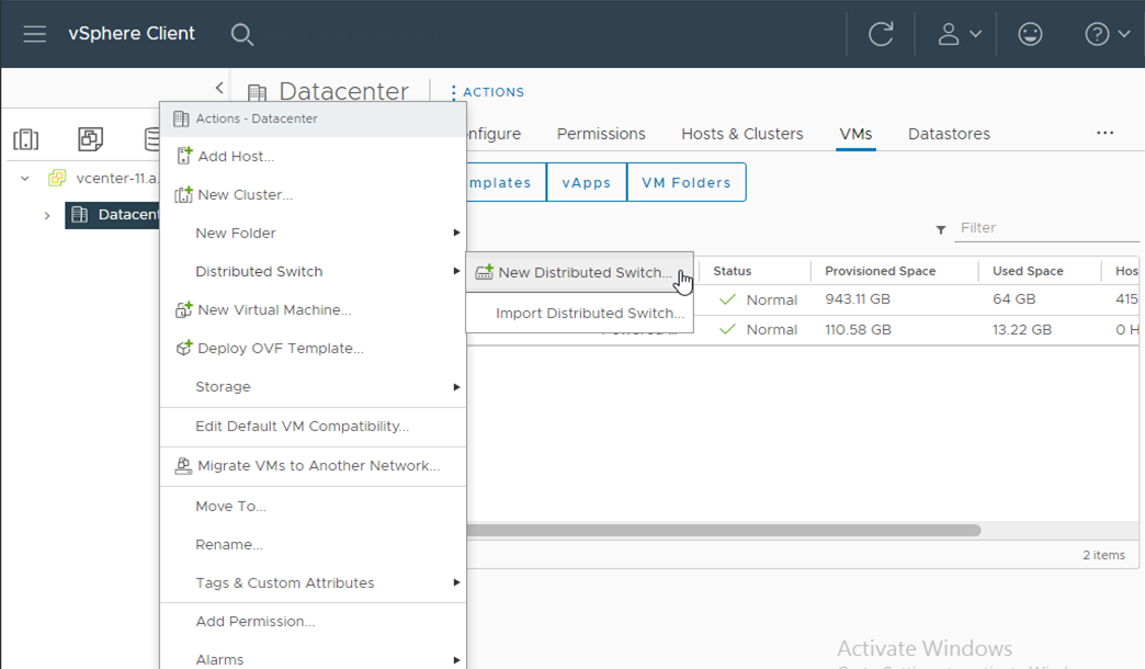
- vSphere Clientへログインし、左インベントリから、[vCenter]をクリックします。インベントリから、[vCenter]>[Inventory Trees]配下の[Networking]をクリックします。インベントリの[Datacenter]を右クリックし、[New Distributed Switch]をクリックします。
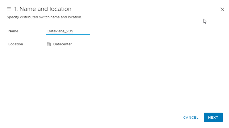
「New Distributed Switch」画面が表示されるので 「1 Name and location」にて、必要事項を入力し、[NEXT]をクリックします。
本書では以下の設定でvDS(データプレーン)を構築しています。
項目 |
既定値 |
設定値 |
Name: |
(空欄) |
DataPlane_vDS |
location: |
Datacenter(変更不可) |
Datacenter |
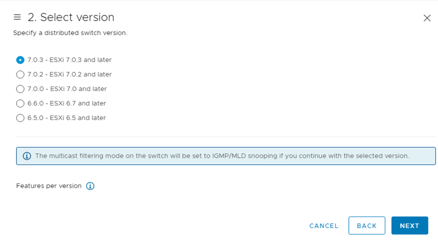
「2 Select version」にて、[Distributed switch: 7.0.3]を選択し、[NEXT]をクリックします。
「3 Configure settings」にて必要事項を入力し、[NEXT]をクリックします。
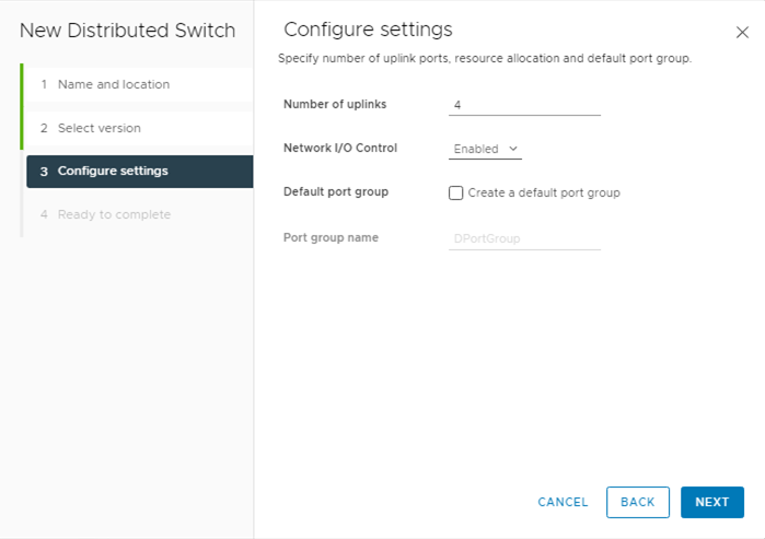
本書では以下の設定でvDS(データプレーン)を構築しています。
項目 |
既定値 |
設定値 |
Number of uplinks: |
4 |
4 |
Network I/O Control: |
Enable |
Enable |
Default port group: |
選択(Create a default port group) |
未選択 |
Port group name: |
DPortGroup |
(空欄) |
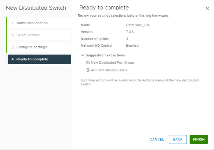
「4 Ready to complete」にて設定内容を確認し、[FINISH]をクリックします。
vDSポートグループ設定
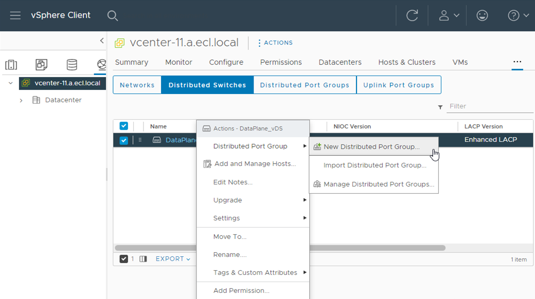
- vSphere Clientのインベントリから、[vCenter]>[Inventory Trees]配下の[Networking]をクリックします。作成したvDSを右クリックし、[New Distributed Port Group]をクリックします。
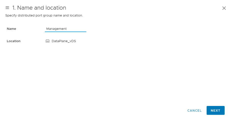
「New Distributed Port Group」画面が表示されるので、「1 Name and location」にて必要項目を入力し、[NEXT]をクリックします。
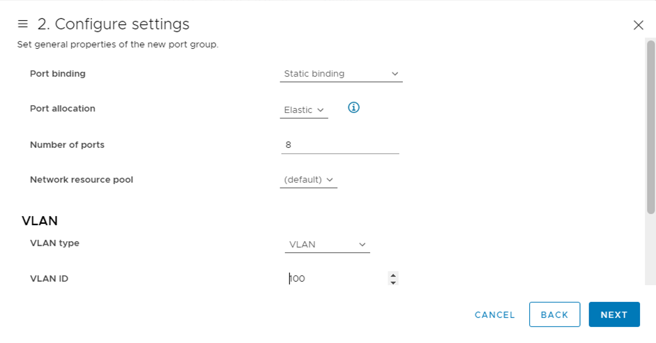
「2 Configure settings」にて必要項目を入力し、[NEXT]をクリックします。
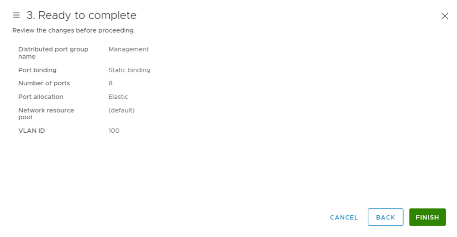
「3 Ready to complete」にて設定に問題ないことを確認し、[FINISH]をクリックします。
すべてのポートグループを同様に追加します。
本書では以下のように入力しています。
Name: |
Management |
DB |
Common Function Gateway |
User Network 1 |
User Network 2 |
vMotion 1 |
vMotion 2 |
ECL Admin Management Network |
Location: |
DataPlane_vDS |
DataPlane_vDS |
DataPlane_vDS |
DataPlane_vDS |
DataPlane_vDS |
DataPlane_vDS |
DataPlane_vDS |
DataPlane_vDS |
Port binding: |
Static binding |
Static binding |
Static binding |
Static binding |
Static binding |
Static binding |
Static binding |
Static binding |
Port allocation: |
Elastic |
Elastic |
Elastic |
Elastic |
Elastic |
Elastic |
Elastic |
Elastic |
Number of Port: |
8 |
8 |
8 |
8 |
8 |
8 |
8 |
8 |
Network resource port: |
(default) |
(default) |
(default) |
(default) |
(default) |
(default) |
(default) |
(default) |
VLAN type: |
VLAN |
VLAN |
VLAN |
VLAN |
VLAN |
VLAN |
VLAN |
VLAN |
Customize default policies configuration: |
100 |
101 |
3 |
100 |
100 |
102 |
102 |
3 |
vMotionポートの追加
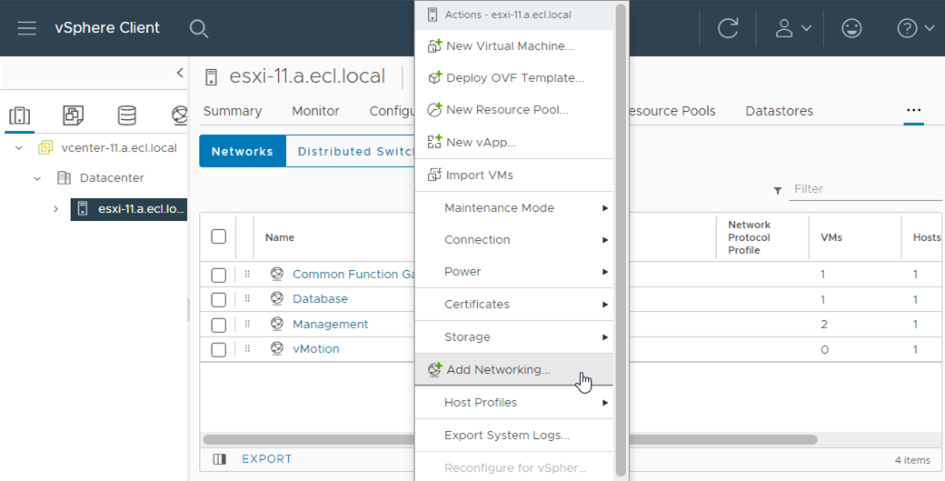
- vSphere Clientのインベントリから、[Home]>[Hosts and cluster]配下の対象ホスト(esxi-11)を選択します。右ペインから[manage]>[Networking]>[VMkernel adapters]と選択、[Add Networking]をクリックし、必要項目を入力して登録します。
本書では以下の設定でvMotionポートの追加設定をしています。
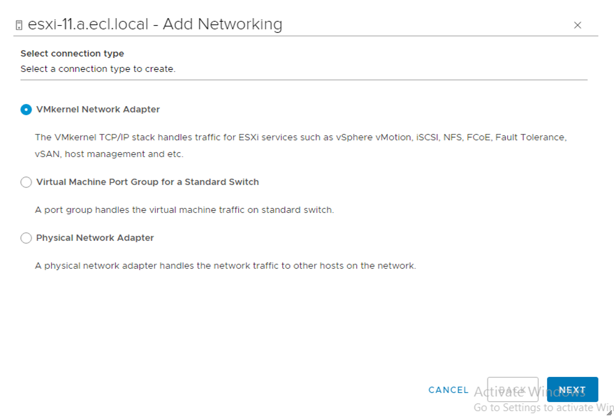
Selection connection type |
VMkernel Network Adapter |
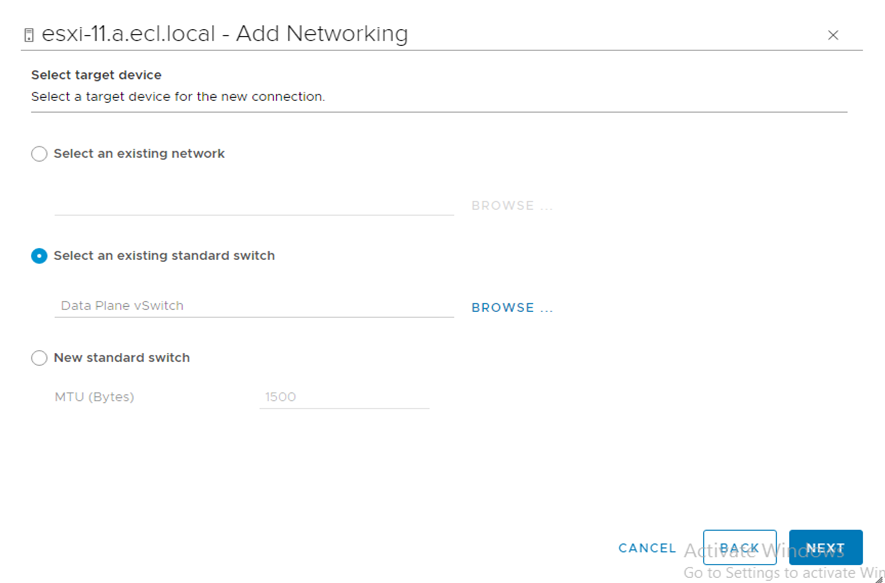
Select target device |
Select an exiting standard switch
DataPlane vSwitch
|
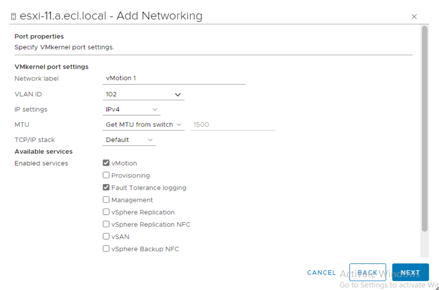
Network label |
vMotion 1 |
Vlan ID |
102 |
IP settings |
IPv4 |
TCP/IP stack |
default |
Enable services |
vMottion trafffic
Fault Tolerance logging
にチェックを入れる
|
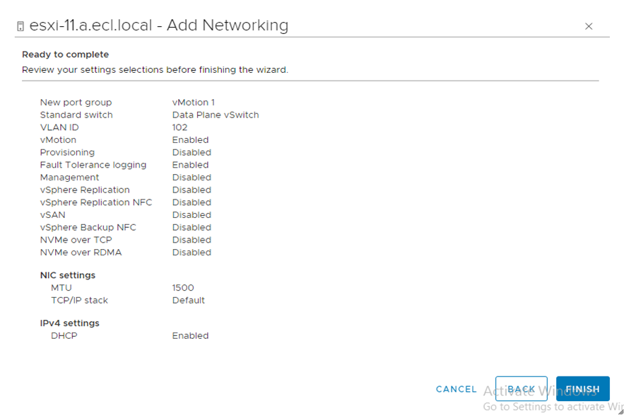
IPv4 settings |
未記入 |
※[Network label]を[vMotion 2]へ変更し、同じ内容で作成する
「Select connection type」にて[VMkernel Network adapter]を選択し、[NEXT]をクリックします
「Select target device」にて[Select an existing standard switch]>[BROWSE...]をクリックし、Data Plain vSwitchを選択後、[NEXT]をクリックします。
「Port properties」にて必要事項を入力し、[NEXT]をクリックします。
「Ready to complete」にて入力内容を確認し、[FINISH]をクリックします。
VMkernel移行
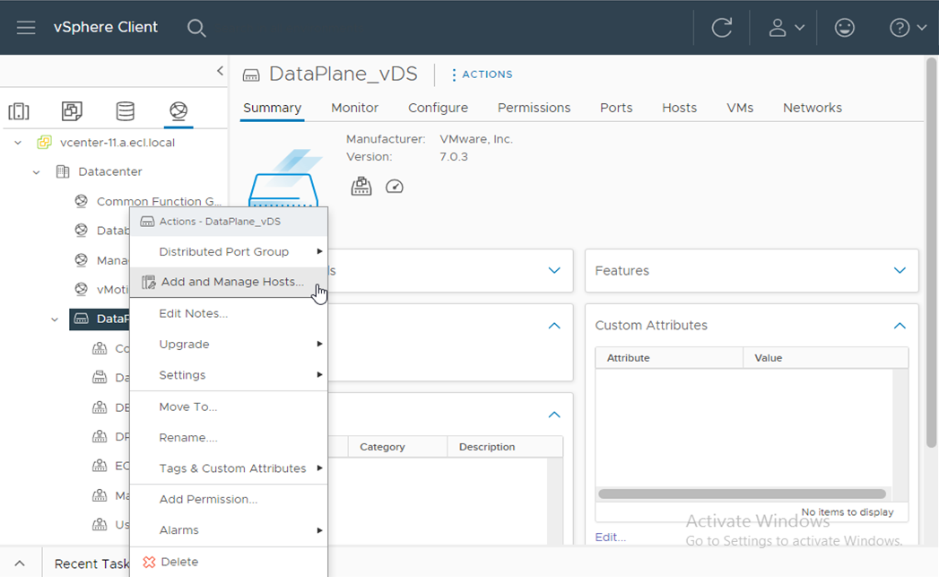
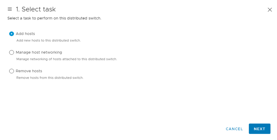
- vSphere Clientのインベントリから、[vCenter]>[Inventory Trees]配下の[Networking]をクリックします。作成したvDSを右クリックし、[Add and Manage Hosts...]をクリックします。
「Add and Manage Hosts」画面が表示されるので、「1 Select task」にて[Add hosts]を選択し、[NEXT]をクリックします。
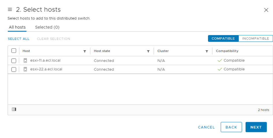
「2 Select hosts」にて、[esxi-11.a.ecl.local]および[esxi-22.a.ecl.local]にチェックを入れ、[NEXT]をクリックします。
「3 Manage physical adapters」にて[vmnic0]を選択し、右側の[Assign uplink]のプルダウンから[uplink 1]を選択、[NEXT]をクリックします。
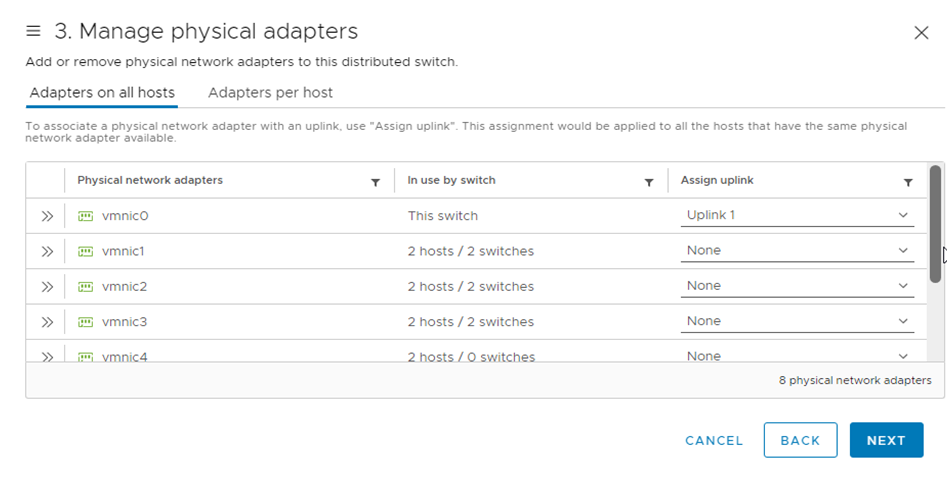
同様にすべてのESXiホストに[uplink]を追加し、[NEXT]をクリックします。
Host/Physical Network Adapters |
On this switch |
In Use by Switch |
Uplink |
Uplink Port Group |
esxi-11.a.ecl.local |
vmnic0 |
Data Plane vSwitch |
Uplink 1 |
DataPlane_vDS-DVUplinks-1009 |
esxi-22.a.ecl.local |
vmnic0 |
Data Plane vSwitch |
Uplink 1 |
Data Plane vSwitch |
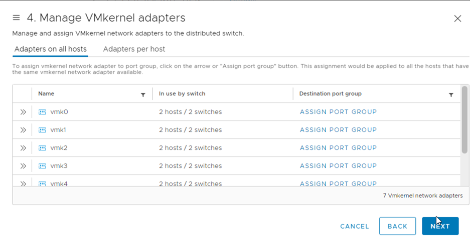
- 「4 Manage VMkernel adapters」にて移行対象のVMkernelポートを選択します。右ペインの[assign port group]から割り当て対象となるポートグループを選択し、右側の[ASSIGN]をクリックします。ポートグループが設定されたら、右ペインの一番内側の×をクリックします。
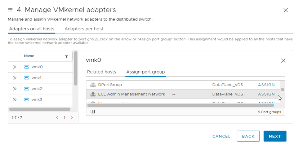
すべてのVMkernelポートに対し同様の手順を実施し、[NEXT]をクリックします。
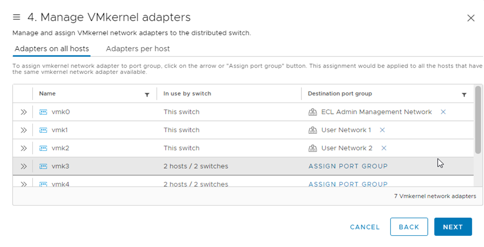
本書では以下の設定でVMkernelポートを設定しています。
On this switch |
vmk0 |
vmk1 |
vmk2 |
vmk5 |
vmk6 |
In Use by Switch |
Data Plane vSwitch |
Data Plane vSwitch |
Data Plane vSwitch |
Data Plane vSwitch |
Data Plane vSwitch |
Source Port Group |
ECL Administrator Management |
User Network 1 |
User Network 2 |
vMotion Network 1 |
vMotion Network 2 |
Destination Port Group |
ECL Administrator Management |
User Network 1 |
User Network 2 |
vMotion Network 1 |
vMotion Network 2 |
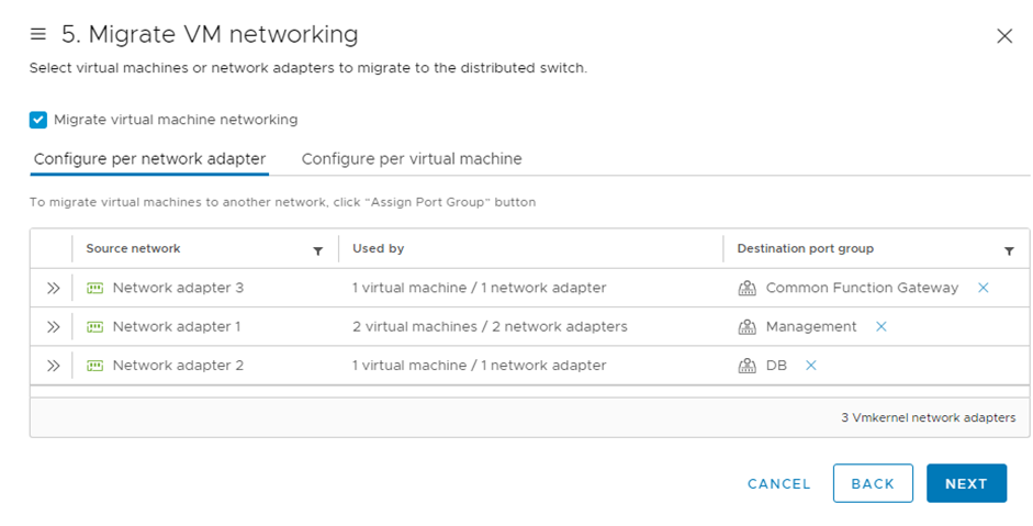
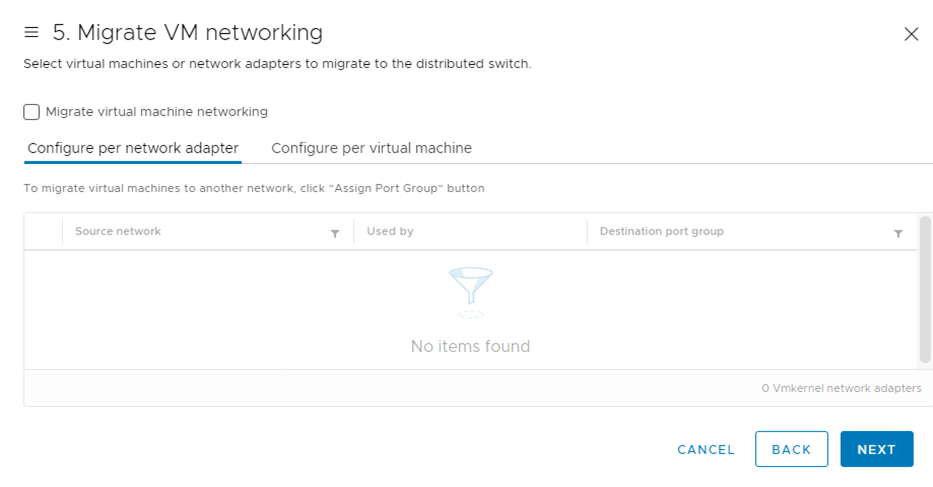
「5 Migrate VM Networking」の[Configure per network adapter]にて、[Source network]をクリックします。対応する[Destination port group]を選択し[NEXT]をクリックします。
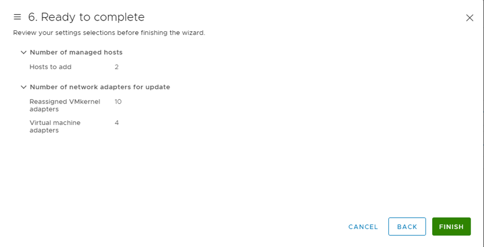
「6 Ready to complete」にて設定を確認し、[FINISH]をクリックします。
仮想マシンポートグループ移行
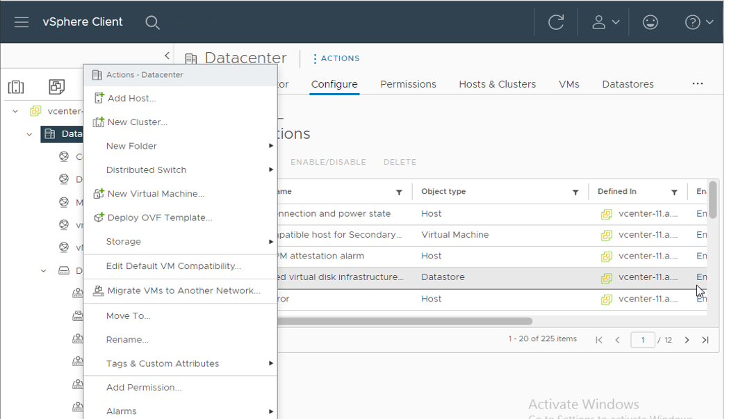
- vSphere Clientのインベントリから、[vCenter]>[Inventory Trees]配下の[Networking]をクリックします。[Datacenter]を右クリックし、[Migrate VMs to Another Network...]をクリックします。
「Migrate VMs to Another Network」画面が表示されるので、「Select source and destination networks」にて必要事項を入力し、[NEXT]をクリックします。
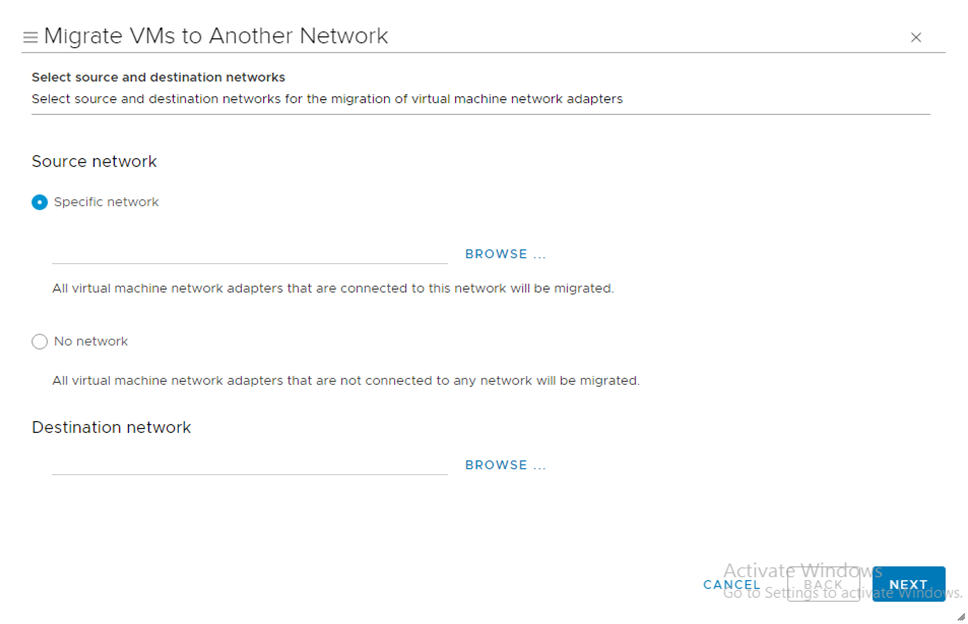
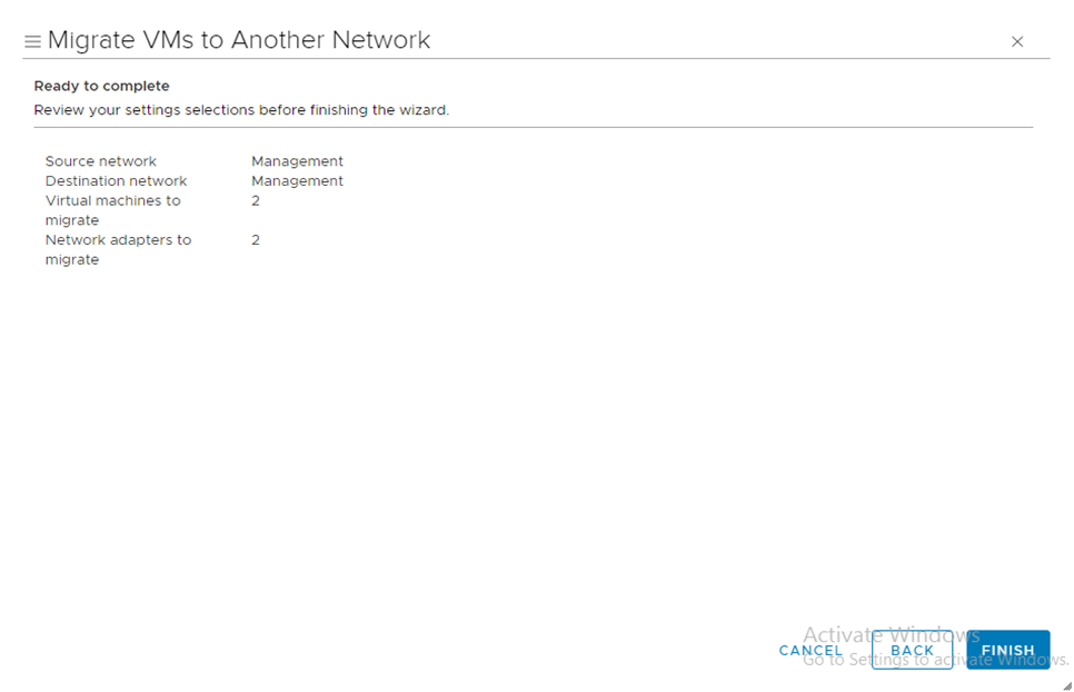
本書では以下の1ポートグループごとに設定しています。
Source network |
|||
Specific network |
Management |
DB |
Common Function Gateway |
Destination network |
|||
Name |
Management |
DB |
Common Function Gateway |
Distributed Switch |
DataPlane_vDS |
DataPlane_vDS |
DataPlane_vDS |
「2 Select VMs to migrate」にて、移行対象のVMすべてにチェックを入れ、[NEXT]をクリックします。
「3 Ready to complete」にて、設定内容を確認し[FINISH]をクリックします。
注釈
同様の手順を、仮想マシンネットワークごとに実施します。
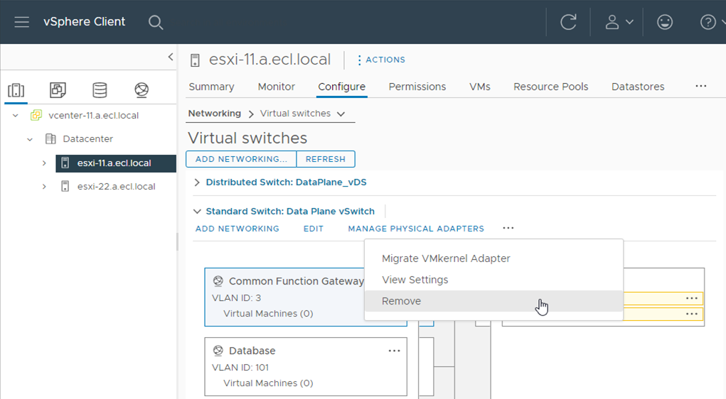
標準仮想スイッチ削除
- vSphere Clientのインベントリから、[Datacenter]配下の[esxi-11.a.ecl.local]を選択し、右側ペインから[Configure]タブをクリックします。[Configure]タブ内の[Networking]>[Virtual switches]をクリックします。削除対象の仮想マシンスイッチを選択し、[Remove]をクリックします。
「Remove Standard Switch」画面が表示されるので、[YES]をクリックします。
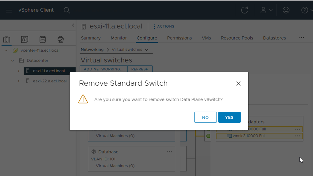
同様の手順を、ESXiホスト、標準仮想スイッチごとに実施します。
本書では以下の標準仮想スイッチを削除しています。
ESXiホスト |
esxi-11.a.ecl.local |
esxi-22.a.ecl.local |
削除対象標準仮想スイッチ |
|
|
vDSへuplinkポート追加
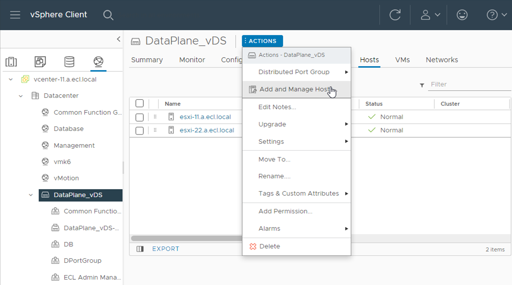
- vSphere Clientのインベントリから、[vCenter]>[Inventory Trees]配下の[Networking]をクリックします。作成したvDSを右クリックし、[Add and Manage Hosts]をクリックします。
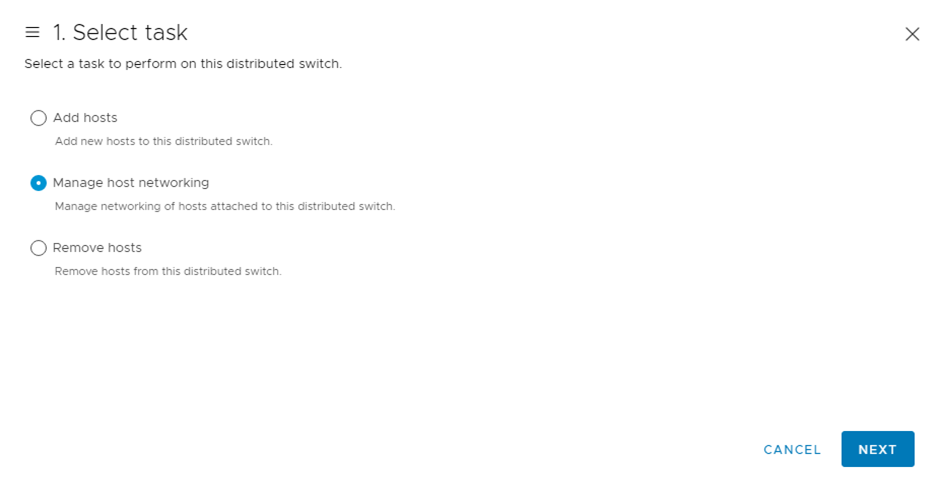
「Add and Manage Hosts」画面が表示されるので、「1 Select task」にて[Manage host networking]を選択し、[NEXT]をクリックします。
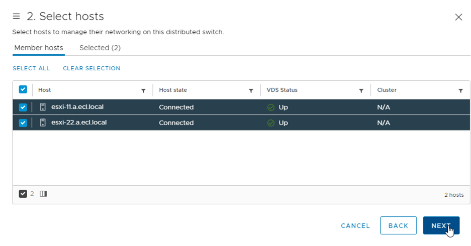
「2 Select hosts」にて表示されたホストすべてにチェックを入れ、[NEXT]をクリックします。
「3 Manage physical adapters」にて、[vmnic3]を選択し、右の[Assign uplink]プルダウンから[uplink 2]を選択し、[NEXT]をクリックします。
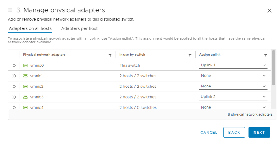
同様にすべてのESXiホストに[uplink]を追加し、[NEXT]をクリックします。
本書では以下の設定でuplinkポートを設定しています。
Host/Physical Network Adapters |
On this switch |
In Use by Switch |
Uplink |
Uplink Port Group |
vCenter-1.a.ecl.local |
|
Data Plane vSwitch |
|
DataPlane_vDS-DVUpl... |
vCenter-1.a.ecl.local |
|
Storage Plane vSwitch |
|
|
vCenter-2.a.ecl.local |
|
Data Plane vSwitch |
|
|
vCenter-2.a.ecl.local |
|
Storage Plane vSwitch |
|
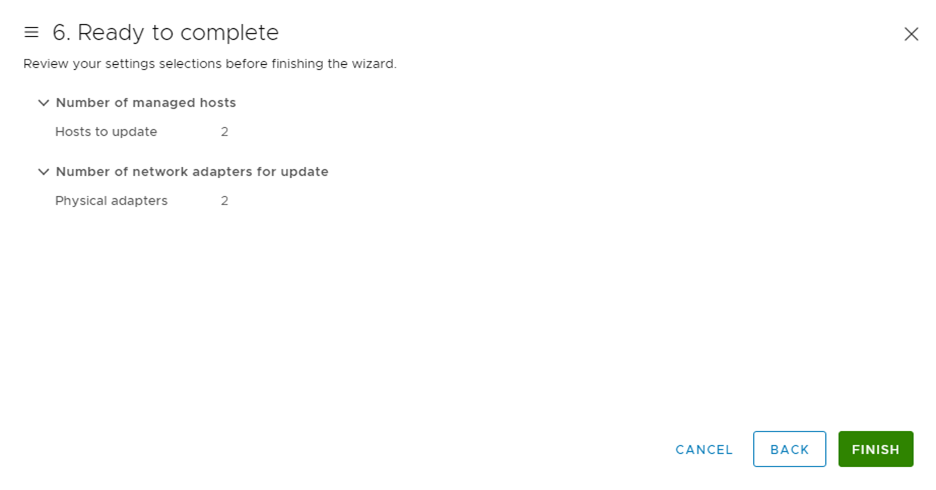
「4 Manage VMkernel adapters」にて、設定を変更せず[NEXT]をクリックします。
「5 Migrate VM networking」にて設定を変更せず[NEXT]をクリックします。
「6 Ready to complete」にて設定を確認し、[FINISH]をクリックします。